Hello everybody,
I am trying to learn some basics about node editing in AS, but there is something that is bugging me. I was trying to move (or translate) a curve node in order to deform the curve segment binded to it.
for that I am trying to use the "Curvature" tool, but it is not working like I need, then I would like to know if there is a way to do what I want.
I am an extensive Corel user, and when you click a node appear two "wires" that you can push or pull to deform a curve and it can bend the segments in symetric mode (it curve both sides segments proportionally) or cusp mode (it curve sides independently).
Seems to me that AS just modify the segments tied to a node in symetrical way. But I would like to know how to make an "S" for instances, that is, bend one segment to a side and other segment to oposite side.
Make sense???
Node editing?
Moderators: Víctor Paredes, Belgarath, slowtiger
See http://www.lostmarble.com/forum/viewtopic.php?t=2803
It is a little long but you will learn a lot.
Don't blame about AS curves to be beizers until you read that. Animation mode of AS needs that kind of curves construction in my opinion.
Regards
It is a little long but you will learn a lot.
Don't blame about AS curves to be beizers until you read that. Animation mode of AS needs that kind of curves construction in my opinion.
Regards

Also check out this thread by forum user Fazek.
http://www.lostmarble.com/forum/viewtopic.php?t=4462
http://www.lostmarble.com/forum/viewtopic.php?t=4462
[url=http://burtabreu.animationblogspot.com:2gityfdw]My AnimationBlogSpot[/url:2gityfdw]

Perhaps also read some background info on Wikipedia on the cubic Bézier curve, which is the type of curve used in many programs, including Anime Studio.
Edit: This cubic Bézier curve looks sooo familiar to us AS users.

Edit: This cubic Bézier curve looks sooo familiar to us AS users.
It also helps to understand how the curves in AS work, at least visually.
It's like circle and ellipses. If you understand how they are constructed, it's much easier to deal with them. If a gardener constructs a circle, he puts a stick in the ground (as a pole), attaches a fixed-length piece of string to it with a loose loop that is somewhat wider than the stick is thick, and uses a loose stick tied at the other end of the string to mark the circle, by going around. With an ellipse, he puts two sticks in the ground (as poles, and BTW at the focal points of the ellipse), puts a fixed-length string with the ends tied together around them, and inserts a third (loose) stick in the looped string to mark half the ellipse, by going around in 180 degrees. He then inserts the loose stick at the other side of the line between the two poles, and goes around the other 180 degrees.
For a cubic Bézier curve (a third order curve), you need to know first how linear and quadratic Bézier curves work.
Linear Bézier curves (first order Bézier curves) are line pieces between two points, P0 and P1, with an interval running from 0 to 1 (fractional numbers). If t is zero, you are in P0, if t is one, your are in P1, and if t is between one and zero, exclusively, you are one the line piece between P0 and P1, where the t is the measure of the distance between P0 and the point B(t) on the line piece.
See this animation from Wikipedia. The linear Bézier curve is shown in red color.

Quadratic Bézier curves (second order Bézier curves) have three control points P0, P1, and P2 with an interval running from 0 to 1. If t is zero, you are in P0, if t is one, you are in P2, and if t is between one and zero, exclusively, you're somewhere on the curve between P0 and P2.
To construct a quadratic Bézier curve, you start by constructing a line piece between P0 and P1 and let construction point Q0(t) run from P0 to P1, where t is the measure of the distance between P0 and Q0(t). This is, in essence, constructing a linear Bézier curve between P0 and P1, with Q0(t) as the point running on the linear Bézier curve.
You do the same for the line piece (linear Bézier curve) between P1 and P2. Q1(t) runs from P1 to P2 in a straight line, and the distance between P1 and Q1(t) depends linearly on the value of t.
The quadratic Bézier curve, going from point P0 to P2 is described by B(t). B(t) is constructed by connected Q0(t) and Q1(t) and putting B(t) on the line piece between Q0(t) and Q1(t), where the distance between Q0(t) and B(t) depends linearly on t.
Here is an animation from Wikipedia to demonstrate this construction. The construction points and the connection between them are shown in green color. The quadratic Bézier curve is shown in red color.

You are seeing Q0 running from P0 to P1, Q1 running from P1 to P2, and B (the Bézier curve) running from Q0 to Q1. The distance between P0 and Q0 depends linearly on t, as do the other distances (between P1 and Q1, and between Q0 and B) depend linearly on t.
For cubic Bézier curves (third order curves), you are using a similar construction, but slightly more complex than for quadratic Bézier curves.
The cubic Bézier curve has four control points, P0, P1, P2, and P3. The curve starts in P0 and ends in P3.
You first will need to construct linear Bézier curves between P0 and P1 (Q0), P1 and P2 (Q1), and P2 and P3 (Q1). Next, you will need to construct points on quadratic Bézier curves, by connecting Q0 and Q1 (R0), and Q1 and Q2 (R1). The first quadratic Bézier curve, denoted as Q0, runs from P0 to P2, and the second quadratic Bézier curve, denoted as Q1, runs from P1 to P3.
Next, you will need to connect R0 with R1, and place B, the actual point on the cubic Bézier curve, at a distance between R0 and R1 that linearly depends on the value of t.
Here is an animation from Wikipedia to demonstrate this construction. The construction points Q0, Q1 and Q2, and the connections between them are shown in green color. The construction points R0 and R1, and the connection between them are show in blue color. The cubic Bézier curve is shown in red color.

Now in Anime Studio, only points P0 and P3 are visible (or "exposed" to the user), and can be dragged by the user. Points P1 and P2 are controlled by the program. Well, that is not entirely true. You, as the user, have some control over P1 and P2, namely trough the curvature feature.
The curvature feature (Curvature tool in the Tool window), lets you determine how far out the points P1 and P2 are from P0 and P3, respectively. If P1 and P2 are located on the line that runs through P0 and P3, the resulting cubic Bézier curve is a straight line.
Where P1 and P2 are, relative to P0 and P3, is therefore a combination of the positions of P0 and P3, the curvature value (all three controlled by the user), and the algorithm the developer of Anime Studio has written. We don't know what this algorithm is (hopefully Fazek can find this out for us), but it seems to depend on the surrounding connected points.
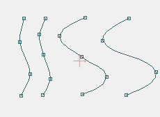
See what happens if you connect points in different ways:

The curve on the left is constructed by dragging a line to the right from point 1 to point 2, putting point 3 on that line, and dragging point 4 out toward the bottom of the screen.
The curve on the right is constructed by dragging a shorter line to the right from point 1 to point 2, and a dragging point 3 to the bottom. Next, point 4 was dragged to the right from point 2 outwards.
You would think this should create the same curve among points 1, 2, 3 and 4, but it doesn't. How (in what order) you connect your points changes the positions of the invisible control points. That's why it is so important to construct your curves correctly, and you should add the points of a curve in the correct order.
This is not so much a problem when a curve is continuous, but when there are branches, as in the above illustration, you need to know how to construct your curves. Is the branch part of a general shape, then add that branch first. Is the branch really a break in a general shape (the start of a new shape), then add that branch later.
So when you manually trace an image, you should first study how the image is constructed, what parts is consists of. If you don't, you are either forced to start anew, or correct your mistake by adding extra points. And then, sometimes an image is so complex, that you can't escape to add a surplus of points.
Remember, the more points you add, the slower it will render. So it's important to keep the point count as low as possible, by adding them intelligently.
It is also the reason why an automated retrace (e.g. when importing Adobe Illustrator files) produces so many points. Most vector drawing programs have there control points exposed to the user. Because AS uses a special method of placing some of those control points, the import filter has to add extra points as padding for the curve. The import filter doesn't understand what has been drawn by a human in the other program, so it tries to add extra points to approximate the original artwork as closely as possible.
You will often see that
It's like circle and ellipses. If you understand how they are constructed, it's much easier to deal with them. If a gardener constructs a circle, he puts a stick in the ground (as a pole), attaches a fixed-length piece of string to it with a loose loop that is somewhat wider than the stick is thick, and uses a loose stick tied at the other end of the string to mark the circle, by going around. With an ellipse, he puts two sticks in the ground (as poles, and BTW at the focal points of the ellipse), puts a fixed-length string with the ends tied together around them, and inserts a third (loose) stick in the looped string to mark half the ellipse, by going around in 180 degrees. He then inserts the loose stick at the other side of the line between the two poles, and goes around the other 180 degrees.
For a cubic Bézier curve (a third order curve), you need to know first how linear and quadratic Bézier curves work.
Linear Bézier curves (first order Bézier curves) are line pieces between two points, P0 and P1, with an interval running from 0 to 1 (fractional numbers). If t is zero, you are in P0, if t is one, your are in P1, and if t is between one and zero, exclusively, you are one the line piece between P0 and P1, where the t is the measure of the distance between P0 and the point B(t) on the line piece.
See this animation from Wikipedia. The linear Bézier curve is shown in red color.
Quadratic Bézier curves (second order Bézier curves) have three control points P0, P1, and P2 with an interval running from 0 to 1. If t is zero, you are in P0, if t is one, you are in P2, and if t is between one and zero, exclusively, you're somewhere on the curve between P0 and P2.
To construct a quadratic Bézier curve, you start by constructing a line piece between P0 and P1 and let construction point Q0(t) run from P0 to P1, where t is the measure of the distance between P0 and Q0(t). This is, in essence, constructing a linear Bézier curve between P0 and P1, with Q0(t) as the point running on the linear Bézier curve.
You do the same for the line piece (linear Bézier curve) between P1 and P2. Q1(t) runs from P1 to P2 in a straight line, and the distance between P1 and Q1(t) depends linearly on the value of t.
The quadratic Bézier curve, going from point P0 to P2 is described by B(t). B(t) is constructed by connected Q0(t) and Q1(t) and putting B(t) on the line piece between Q0(t) and Q1(t), where the distance between Q0(t) and B(t) depends linearly on t.
Here is an animation from Wikipedia to demonstrate this construction. The construction points and the connection between them are shown in green color. The quadratic Bézier curve is shown in red color.
You are seeing Q0 running from P0 to P1, Q1 running from P1 to P2, and B (the Bézier curve) running from Q0 to Q1. The distance between P0 and Q0 depends linearly on t, as do the other distances (between P1 and Q1, and between Q0 and B) depend linearly on t.
For cubic Bézier curves (third order curves), you are using a similar construction, but slightly more complex than for quadratic Bézier curves.
The cubic Bézier curve has four control points, P0, P1, P2, and P3. The curve starts in P0 and ends in P3.
You first will need to construct linear Bézier curves between P0 and P1 (Q0), P1 and P2 (Q1), and P2 and P3 (Q1). Next, you will need to construct points on quadratic Bézier curves, by connecting Q0 and Q1 (R0), and Q1 and Q2 (R1). The first quadratic Bézier curve, denoted as Q0, runs from P0 to P2, and the second quadratic Bézier curve, denoted as Q1, runs from P1 to P3.
Next, you will need to connect R0 with R1, and place B, the actual point on the cubic Bézier curve, at a distance between R0 and R1 that linearly depends on the value of t.
Here is an animation from Wikipedia to demonstrate this construction. The construction points Q0, Q1 and Q2, and the connections between them are shown in green color. The construction points R0 and R1, and the connection between them are show in blue color. The cubic Bézier curve is shown in red color.
Now in Anime Studio, only points P0 and P3 are visible (or "exposed" to the user), and can be dragged by the user. Points P1 and P2 are controlled by the program. Well, that is not entirely true. You, as the user, have some control over P1 and P2, namely trough the curvature feature.
The curvature feature (Curvature tool in the Tool window), lets you determine how far out the points P1 and P2 are from P0 and P3, respectively. If P1 and P2 are located on the line that runs through P0 and P3, the resulting cubic Bézier curve is a straight line.
Where P1 and P2 are, relative to P0 and P3, is therefore a combination of the positions of P0 and P3, the curvature value (all three controlled by the user), and the algorithm the developer of Anime Studio has written. We don't know what this algorithm is (hopefully Fazek can find this out for us), but it seems to depend on the surrounding connected points.
See what happens if you connect points in different ways:
The curve on the left is constructed by dragging a line to the right from point 1 to point 2, putting point 3 on that line, and dragging point 4 out toward the bottom of the screen.
The curve on the right is constructed by dragging a shorter line to the right from point 1 to point 2, and a dragging point 3 to the bottom. Next, point 4 was dragged to the right from point 2 outwards.
You would think this should create the same curve among points 1, 2, 3 and 4, but it doesn't. How (in what order) you connect your points changes the positions of the invisible control points. That's why it is so important to construct your curves correctly, and you should add the points of a curve in the correct order.
This is not so much a problem when a curve is continuous, but when there are branches, as in the above illustration, you need to know how to construct your curves. Is the branch part of a general shape, then add that branch first. Is the branch really a break in a general shape (the start of a new shape), then add that branch later.
So when you manually trace an image, you should first study how the image is constructed, what parts is consists of. If you don't, you are either forced to start anew, or correct your mistake by adding extra points. And then, sometimes an image is so complex, that you can't escape to add a surplus of points.
Remember, the more points you add, the slower it will render. So it's important to keep the point count as low as possible, by adding them intelligently.
It is also the reason why an automated retrace (e.g. when importing Adobe Illustrator files) produces so many points. Most vector drawing programs have there control points exposed to the user. Because AS uses a special method of placing some of those control points, the import filter has to add extra points as padding for the curve. The import filter doesn't understand what has been drawn by a human in the other program, so it tries to add extra points to approximate the original artwork as closely as possible.
You will often see that
- you can delete points without changing the general shape (too much)
- tracing the image yourself is much more efficient, because you understand how to draw
Hi,
I understand. The fact is that I was looking for the "exposed controls" that doesnt exists in AS. Instead, I should add more nodes.
This is just a different approach, although I will need to acostumate with that since even CorelDraw, Illustrator and Flash (that I am more comfortable to work because years and years) have these controls.
However, I believe (and I have heard it several times here) that's done this way in AS because the fact that shapes work better this way when distorted in the animation.
Thanks to everybody!
PS: From now on you will find a few basic questions like that, since the AS environment is 100% new for me, and my character animation knowledge is ZERO!!!